Gfci Breaker Wiring Diagram Cadician's Blog
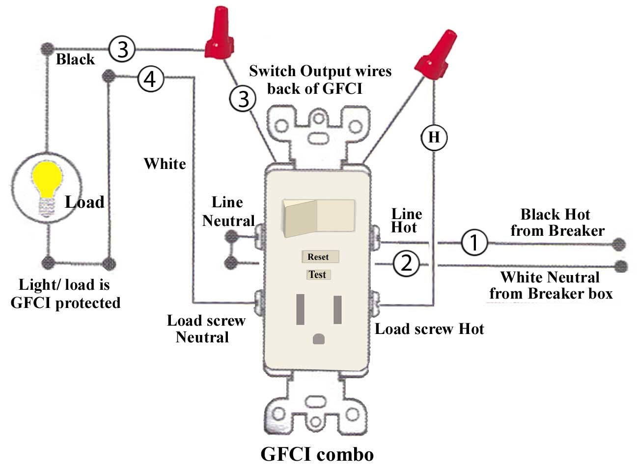
This page contains wiring diagrams for a ground fault circuit interrupter (gfci) with a built in switch, often called a gfci outlet switch combo. This device can be used for ground fault protection near water sources such as in a kitchen or bathroom where space is a minimum and both devices are needed.

Square D Gfci Breaker Wiring Diagram Free Wiring Diagram
Step 2. With the wires twisted together and secured with wire nuts, insert them into the side terminals of the GFCI outlet. The black wires go on the brass screws, and the white wires go on the silver screws. If there is a green grounding wire, it will go on the green grounding screw.

Wiring Gfci Schematic electrical How do I install a GFCI receptacle
( See Diagram A ). Replace the receptacle, screw it back into the box, and attach the cover plate. Turn the power back on at the circuit-breaker panel. Plug a clock radio or light into the outlet. Test the GFCI by pressing the Black "Test" button on the outlet.
Cooper Gfci Wiring Diagram
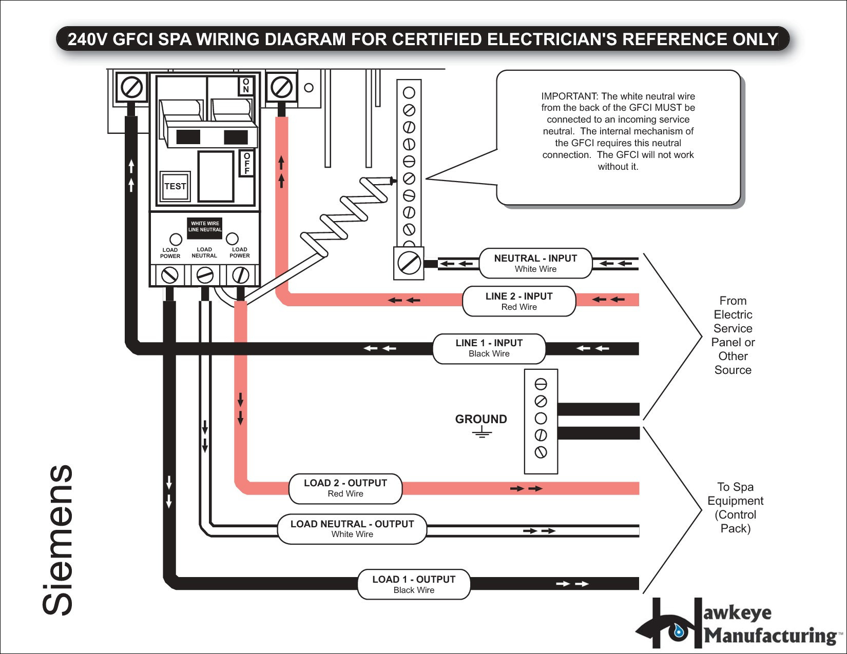
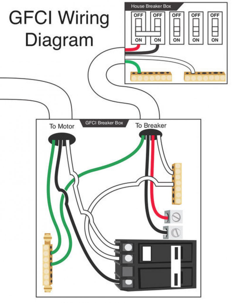
Contents Wiring a GFCI circuit breaker is similar to how you would wire a regular (non-GFCI) one, except it has an extra wire attached directly. If you're unsure how or what the extra wire is, this guide will help you wire the GFCI breaker properly and safely.

Gfci Circuit Breaker Wiring Diagram Electrical Diagram, Electrical
The internal wiring diagram of a GFCI outlet consists of several key components. Firstly, there is the line side, which connects to the power supply. This includes the hot wire (black), the neutral wire (white), and the ground wire (green or bare copper). The load side, on the other hand, connects to downstream outlets or devices.
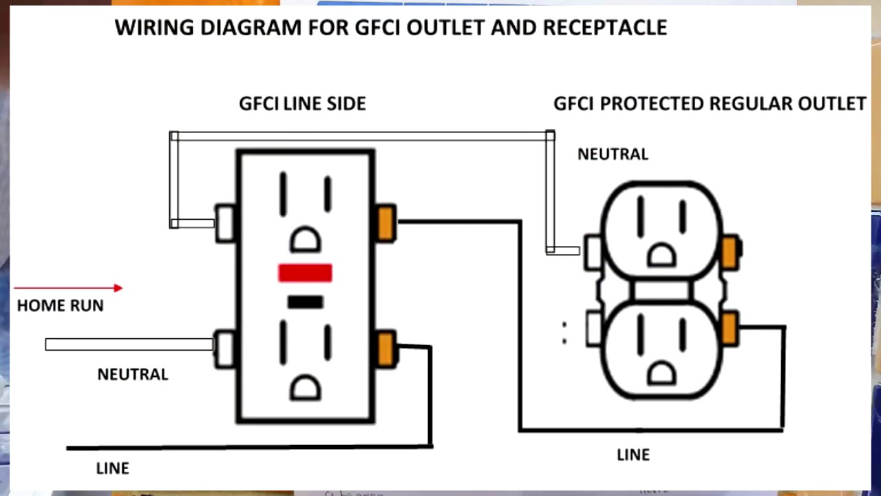
GFCI OUTLET WIRING AND RECEPTACLE (English). YouTube
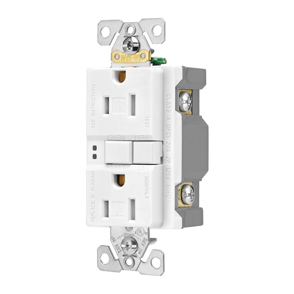
Steps for a GFCI Outlet Wiring Upgrade. First, turn off the power to the circuit you'll be working on. Take off the cover plate and unscrew the outlet from the box. Disconnect the wires and remove the old outlet. At the back of the GFCI are screw terminals marked "load" and "line.". The single screw at the bottom is the grounding screw.

Gfci Receptacle Wiring Diagram Free Wiring Diagram
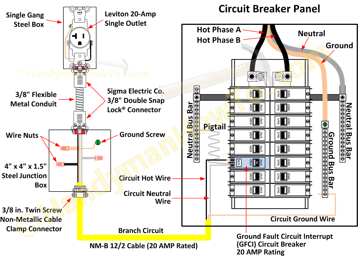
11 5 minutes read Single Phase and Three Phase RCD and GFCI Wiring Circuit Diagrams and Installation Table of Contents GFCI or RCD or RCCB or ELCB? Wiring a Single Pole GFCI Circuit Breaker Wiring a Two Poles GFCI Circuit Breaker Wiring a Three Poles GFCI Circuit Breaker Wiring a Four Poles RCBO or GFCI Circuit Breaker (Three Phase RCCB Wiring)

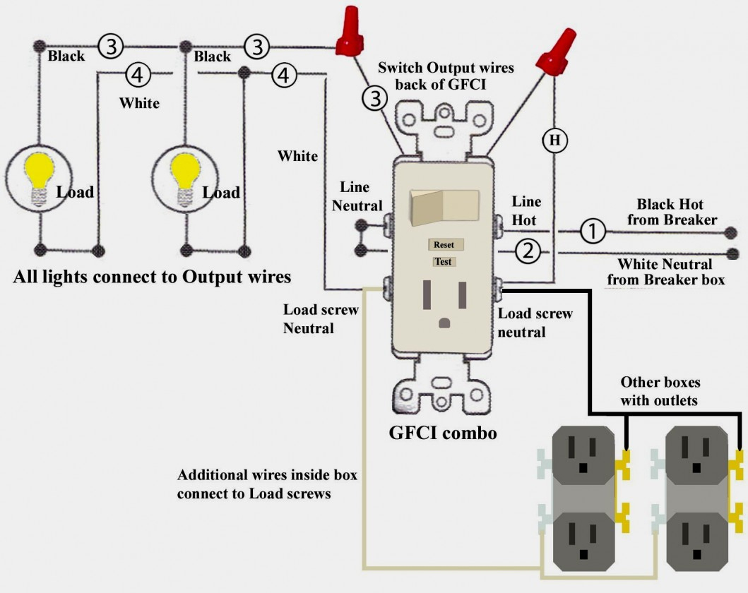
Gfci Outlet With Switch Wiring Diagram Wiring Diagram
A GFCI (Ground Fault Circuit Interrupter) outlet—also known as a GFI outlet—is an outlet that monitors the balance of electricity that goes through a circuit. In the event of a short, GFCI outlets cut off the electricity to the outlet, preventing damage to the circuit.
wiring diagram for outlet with switch 9 practical electrical outlet
Electrical 101 GFCI and AFCI Load Wiring Power is connected to the GFCI or AFCI line side. Protected outlet (s) will be connected to the GFCI or AFCI load side as shown below. Ground connection is not shown. *Line and load terminal locations can differ between GFCI or AFCI outlet brands.
4 Wire Gfci Wiring Data Wiring Diagram Schematic Gfci Wiring
• For a box with no grounding terminal (diagram not shown): Connect the LINE cable's bare copper (or GREEN) wire directly to the grounding terminal on the GFCI receptacle. • For a box with a grounding terminal (diagram shown above): Connect a 6-inch bare copper (or GREEN) 12 or 14 AWG wire to the grounding terminal on the ThisGFCI.
Cooper Gfci Outlet Wiring Diagram Wiring23
Locate the main circuit breaker panel and find the breaker that corresponds to the circuit. Flip the breaker to the "off" position to ensure there is no electricity flowing to the area. 2. Prepare the Wiring. Next, prepare the wiring by stripping the insulation off the ends of the wires using wire strippers.
Wiring A Gfci Plug
A GFCI (ground fault circuit interrupter) is a special type of outlet that detects dangerous ground faults and immediately turns off the power to stop shocks. You can replace almost any electrical outlet with a GFCI outlet. Correctly wired GFCIs will also protect other outlets on the same circuit.

Gfci Receptacle Wiring Diagram Free Wiring Diagram
Learn how to install and use Eaton's GFCI receptacles, which provide reliable and safe protection from electrical hazards in various settings. This PDF guide also covers the latest updates from the NEC 2020 code and offers tips and best practices for GFCI installation.
Three Wire Gfci Diagram Wiring Diagram Detailed Gfci Breaker Wiring
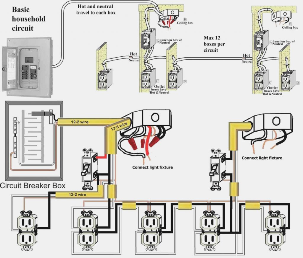
2 Tools for Wiring a GCFI Outlet GFCI outlets can be used several ways inside or outside a home. For example: An entire circuit can be protected by a single GFCI device if the GFCI receptacle is the first outlet on that circuit.

Wiring Gfci Outlet Diagram Brilliant Gfci Outlet Wiring Diagram Popular
The wiring diagram for a GFCI outlet includes the necessary steps and connections to ensure proper installation. It outlines how to connect the incoming and outgoing wires, as well as the correct placement of the line and load terminals. By following the diagram carefully, homeowners and electricians can install a GFCI outlet correctly..
Gfci Outlet Wiring Diagram Electrical Engineering Books
The Best 3 Way Switch Explanation Ever! Terry Peterman 4M views 5 years ago
